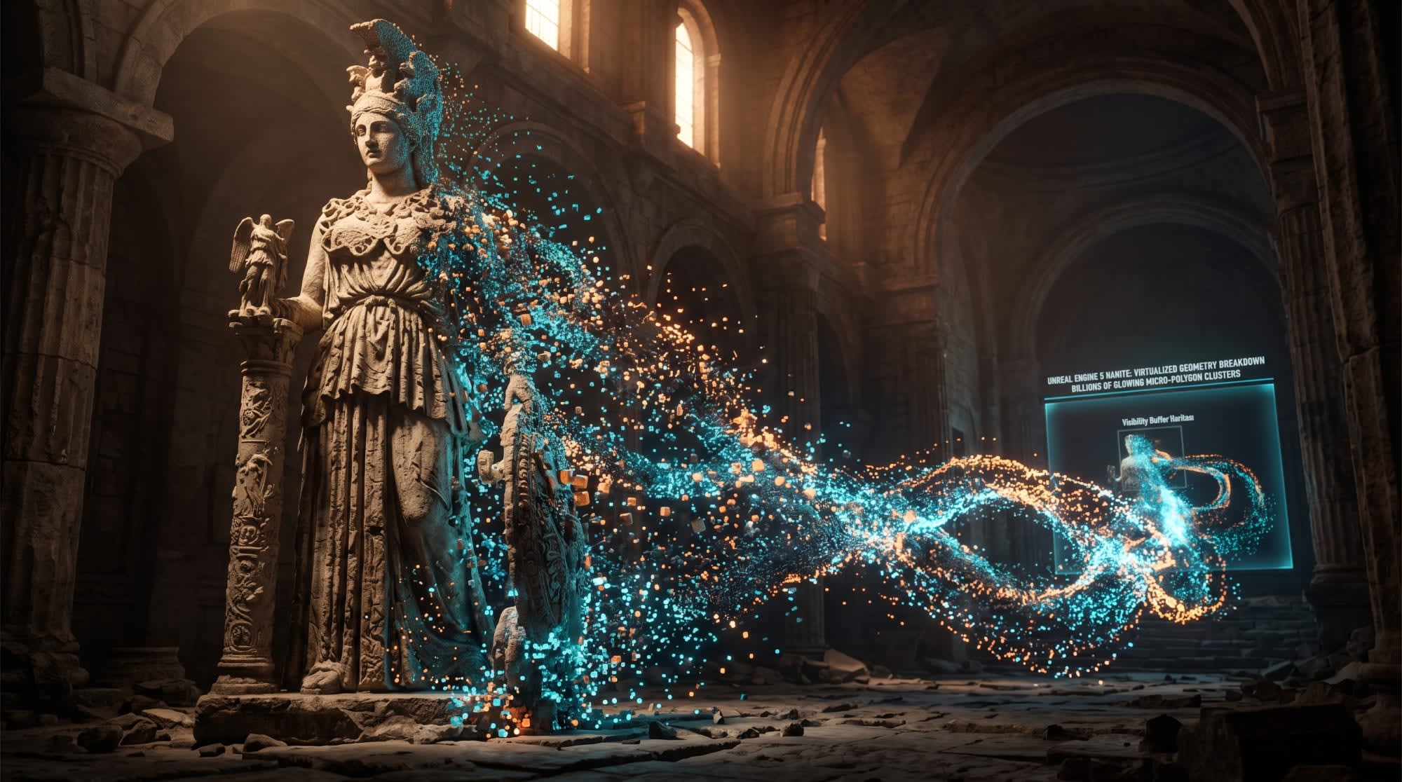
Unreal Engine 5 Nanite Architecture: Comprehensive Technical Analysis, Optimization Strategies, and PlayStation 5 Development Guide
Fundamentals of Virtualized Micropolygon Geometry and Paradigm Shift
One of the biggest constraints persisting for decades in the real-time rendering technologies and computer graphics industry is the inevitable bottlenecks created by polygon budgets and draw call counts in the communication between the central processing unit (CPU) and the graphics processing unit (GPU) for efficient utilization of hardware resources. 1 In traditional game development workflows, 3D artists and technical directors had to manually perform topology optimization, create Level of Detail (LOD) chains, and bake high-resolution details into Normal Maps to transfer high-detail models (such as cinema-quality ZBrush sculptures, laser scans, or photogrammetry data) into game engines. 1 This process created a grueling workload that both extended the production schedule and artificially trapped the level of detail on the screen within limits due to memory constraints. 1 Nanite technology, which became an industry standard with Unreal Engine 5 (UE5), is a virtualized micropolygon geometry system that fundamentally eliminates these traditional barriers. 1 Nanite removes polygon budgets as a technical limitation, allowing source files consisting of billions of film-quality polygons to be imported into the scene in real time without requiring any manual LOD processing. 1 The system is designed to process only the details visible at that moment by the player's camera on the screen; no triangle or geometry piece smaller than the pixel size is rendered unnecessarily. 3 This technology replaces the traditional rendering pipeline entirely with a GPU-driven data streaming architecture by providing a continuous, fluid, and seamless automatic LOD system. 1 Nanite's core innovations are gathered under four main headings 1:
Virtualized Geometry: The entire scene is treated as a single massive static mesh, and only the parts visible on the screen are included in processing.
Automatic Level of Detail (LOD): Instead of gradual and discrete LOD changes (LOD popping), a seamless, fluid detail change is provided depending on distance and screen resolution.
GPU-Driven Pipeline: Draw calls and culling operations are taken away from the CPU and delegated to the parallel processing power of the GPU.
Efficient Streaming: Memory streaming is provided directly via SSD, loading only the required geometry data into memory on the fly.
This research report examines the in-depth working principles of the Nanite system, the steps required for project integration, optimization requirements, how bottlenecks will be overcome, and game development dynamics specifically targeting the PlayStation 5 (PS5) platform, which boasts unmatched hardware-level compression and high-speed data streaming (I/O), within a comprehensive analytical framework.
Nanite Technical Architecture and Data Structures
The philosophy lying at the core of the Nanite system is to treat geometry data not as massive static meshes trying to fit within memory limits, but as fragmented data sets that stream dynamically and are managed on-demand, just like virtual texturing. 3 While traditional engines try to load and process the entire object into memory even if only a small part of it is within the camera's field of view (frustum), Nanite evaluates this visibility at a millimetric pixel precision. 3
Hierarchical Cluster Structure
During the import phase, Nanite algorithms analyze 3D models and divide them into hierarchical cluster trees. 1 Each processed static mesh is split into small data packets (clusters) consisting of exactly 128 triangles to deliver the best performance at the hardware level. 1 This fixed size of 128 triangles is an optimal unit specifically chosen to fully comply with the wavefront or warp sizes of modern GPUs, aiming for maximum processing efficiency from parallel processing units and cache limits. 1 These clusters form a Directed Acyclic Graph (DAG)-like Tree Data Structure among themselves, containing bounding box information, geometric error metrics for screen space LOD selection, and parent-child relationships. 1 As the camera approaches or moves away from the relevant object, the system navigates this tree structure in real time, deciding for each screen region which cluster best matches the pixel density on the screen. 1 Unlike traditional approaches, the entire object does not change abruptly. Instead of a discrete LOD change, different regions on the object surface can be processed simultaneously at different cluster detail levels and merge smoothly from the edges without creating any visual tearing or cracks in hardware rasterization. 3
Visibility Buffer and Decoupled Shading
The most critical structure that enables Nanite to overcome CPU bottlenecks and revolutionizes modern rendering architectures is moving a large portion of the rendering pipeline directly to the GPU and replacing traditional Forward or Deferred shading logic with the "Visibility Buffer". 1 The concept of the visibility buffer in Nanite's render loop works as follows: In traditional G-Buffer structures, massive amounts of data such as color, normal, and roughness are written to memory for every pixel while calculating pixels. Nanite, instead, records only a 32-bit or 64-bit ID number (Primitive ID and Cluster ID) for each pixel on the screen. 1 This buffer memory contains no color or shading data; it is merely a reference map indicating which triangle and which cluster are visible at that specific pixel on the screen. 1 After the visibility buffer is completely filled, material data is called only once for each pixel in the screen space, and the shading operation is performed. Thanks to this "decoupled" architecture, material calculations are not performed unnecessarily for millions of triangles that remain behind the camera, are hidden behind another object, or make no contribution to the final image. This completely eliminates the "Overdraw" problem, which is one of the biggest enemies of the GPU, on a material calculation basis. 9

GPU-Driven Culling Mechanisms
In the Nanite architecture, culling operations are not performed on an actor basis on the CPU as they are in traditional engines. Traditional draw call preparations on the CPU side are completely bypassed, and the culling process is delegated directly to compute shaders within the GPU. 10 During the occlusion culling phase, Nanite uses a structure called HZB (Hierarchical Z-Buffer), where various depth levels (mipmaps) are stored logarithmically in screen space. 9 HZB compares the bounding box of each 128-triangle cluster with the depth data in screen space. 9 If a cluster remains behind another object in the scene, it is immediately discarded from the rendering process. This culling is so precise that because it is done on a cluster basis rather than an object basis, while clusters belonging only to the parts of trees in a massive forest that remain behind a mountain are culled, the leaf clusters spilling over the mountain peak continue to be processed. 8
Rasterization Paths: Software and Hardware Processing Dynamics
Instead of using a uniform processing unit to convert triangles into screen pixels (rasterization), Nanite uses two separate raster path choices decided dynamically based on the triangle's size on the screen and material properties. 9 Performance optimization relies on establishing a perfect balance between these two paths.
Software Raster Path
Software Rasterization is Nanite's most efficient, fastest, and most innovative core processing path. 9 This path comes into play when triangles are smaller than a pixel (sub-pixel) or exactly one pixel in size on the screen. 9 In this scenario, Nanite completely bypasses the GPU's hardware triangle drawing units and executes the process via Compute Shaders. Pixels are written to the visibility buffer at an extraordinary speed using 64-bit atomic interlocks. When the Raster Bins visualization mode is opened from the developer console with the r.Nanite.Visualize.Advanced 1 or r.nanite.showmeshdrawevents 1 command, clusters passing through software rasterization are shown in blue. 9 In a well-optimized scene, the overwhelming majority of the geometry should target being blue. 9
Hardware Raster Path
Hardware Rasterization is the classic GPU drawing method that comes into play when triangles are larger than one pixel on the screen or when special material attributes that Nanite's compute-based software rasterization cannot process are used. 9 This path is shown in red in visualization modes. 9 It is normal for the system to switch to hardware rasterization, especially when the camera approaches a massive wall, as triangles will become larger than pixels. 9 However, if objects or micropolygons distant from the camera still appear in red, this indicates that a "Hardware Fallback" is occurring, which is a serious optimization problem. 9 The biggest reason for unwanted drops into hardware rasterization is the use of masked, transparent, or complex materials with deformation offsets. 9
Raster Bins and Material Management
The heart of Nanite performance is less about the geometry itself and more about how the materials applied onto the geometry are distributed into virtual boxes called "Raster Bins". 9 Nanite takes all standard, opaque materials that do not contain any pixel depth offset (PDO) or world position offset (WPO) into a single massive Raster Bin, and the system processes this box at lightning speed in a single pass. 9 However, when using materials that contain heavy WPO used for displacement, masking (masked/alpha test), or wind effects, these objects are removed from Nanite's fast pass path, causing a separate and independent Raster Bin to be created for each material type. 9
Performance ClassMaterial Type and FeatureNanite Effect and Processing StatusStrategic Developer RecommendationBest (Best)Pure materials without Opaque, WPO, PDO, or Displacement offset.Blended within a single Raster Bin. Software Rasterization runs actively, draw call cost is close to zero.9More than 90% of environmental designs, buildings, and hard surfaces in the project should definitely consist of this type.9Good (Good)Opaque, but with minimal WPO (World Position Offset).Since WPO is used, static clusters start to be calculated separately on the GPU. Culling becomes difficult as bounding boxes will change due to movement.WPO movement distance must definitely be clamped to prevent bounding box corruption and incorrect culling.3 Deformation should be baked if static.9Okay (Okay)Masked (Masked/Transparent edges, Alpha Cutout).Mandatory fallback to Hardware Raster Path. Causes severe "Overdraw" as a result of continuous evaluation of empty pixels.Used in classic leaf or fence modeling, but must be used very sparingly as it hurts performance.8Worst (Worst)Complex Deformed Materials (Heavy WPO + PDO).Each variation creates a separate Raster Bin. Increases state changes, instantly pushing frame times beyond budget limits.Must definitely be disabled immediately on distant objects (LOD fallback) or alternative modern approaches such as Nanite Skinning coming with UE 5.7 should be pursued.9
Having too many Raster Bins means increased state changes on the GPU and increased draw call variations, which severely slows down the GPU.9 In a project targeted for 60 FPS (16.66 ms per frame), it is mandatory to keep the VisBuffer operation under 4 ms and the BasePass operation under 3 ms; otherwise, there will be no time left for other systems such as post-processing, Lumen, and artificial intelligence.7
Nanite Integration: How to Use It in Projects?
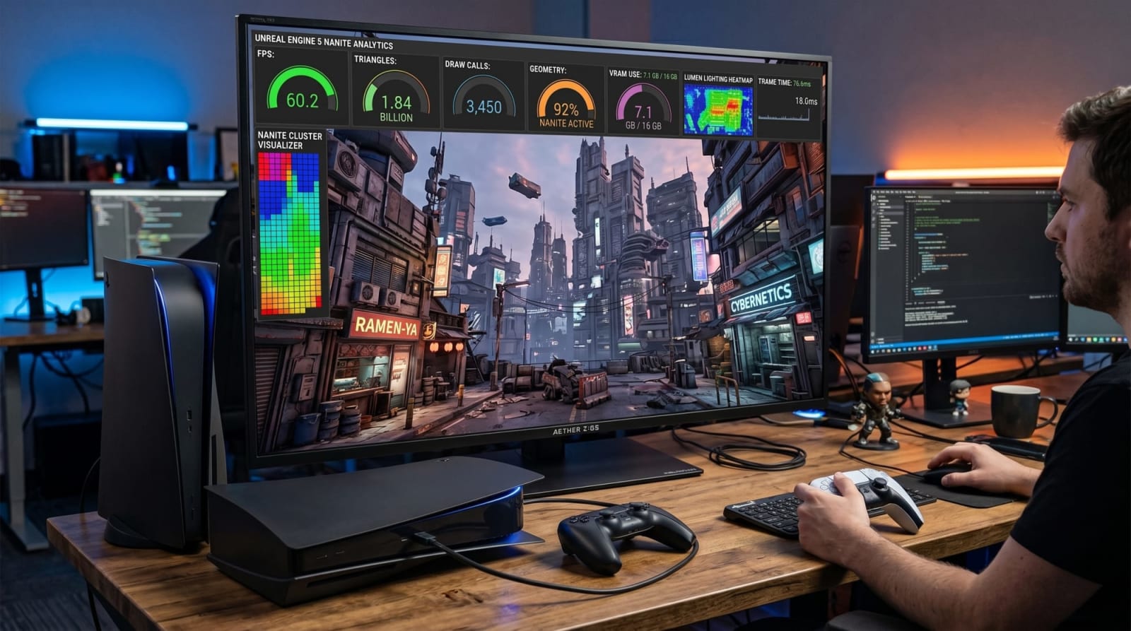
Nanite integration is designed to be incorporated into existing Unreal Engine game development workflows with minimal friction. Eliminating legacy manual LOD generation or normal map baking processes, this system automatically optimizes performance when configured correctly.1
Geometry Types and Supported Components
For a geometry to benefit from Nanite capabilities, this feature must be enabled during the import stage or afterwards through the Static Mesh Editor.3 In current versions of Unreal Engine 5, the types of components supported by Nanite have been significantly expanded:
● Static Meshes: Any Static Mesh included in the project can be converted by checking the "Enable Nanite Support" option inside the Editor. In massive scenes with thousands of objects, the entire library can be transitioned to the Nanite format simultaneously via batch-enable through the Content Browser.3 These meshes are the primary target audience of the Nanite system.
● Skeletal Meshes: While earlier UE5 versions only supported static objects, thanks to the Skeletal Mesh API supports introduced in UE 5.3 and later versions, dynamically deforming (animated) characters, creatures, and vehicles can also be used with Nanite.3 The biggest innovation for skeletal meshes is that only a single draw call is generated for the entire mesh. Nanite Skeletal Meshes operate by using animation LODs instead of classical geometry LODs.3
● Spline Meshes and Landscape: Nanite natively supports Spline Meshes that deform along curves such as roads, pipelines, and walls, as well as wide open-world Landscape topology (via Nanite Tessellation).3 Minor displacement details on grounds can be achieved directly through materials, without creating polygonal density and without degrading performance.3
● Instanced Static Meshes (ISM / HISM): Objects with millions of copies (for example, rocks in a massive forest or bricks of buildings) are rendered with a single memory footprint thanks to Nanite's visibility buffer. However, it should be kept in mind that the maximum number of Nanite instances that can exist in a scene is hardware-limited to 16 million.3
Fallback Mesh Generation and Its Role
When the "Build Nanite" checkbox is checked while generating Nanite data, the engine automatically derives a simplified geometry with a traditional polygon count called a "Fallback Mesh" alongside the high-detail mesh.13
The reason for this fallback mesh's existence is vital: Nanite's GPU-driven rasterization system cannot be used directly for complex physics collision calculations, precalculated lightmaps with Lightmass (baked lighting), and most importantly, hardware ray tracing (hardware ray tracing / Lumen HWRT) reflections.13 The CPU-side logical systems of the game engine need this traditional triangle data. The detail level of the fallback mesh can be controlled by modifying the "Fallback Relative Error" parameter.3 As the error rate is lowered, the polygon count of the fallback mesh increases, which ensures that hardware ray tracing reflections (Lumen Hit Lighting) are calculated more accurately, but it also increases memory (VRAM) usage at the same rate.14
Nanite Foliage: Voxel and Assembly Systems Coming with UE 5.6/5.7
In game engines, forested areas and dense vegetation have long been considered Nanite's most vulnerable point due to the numerous overlapping transparent (masked) leaf surfaces.15 Traditional grass or leaf modeling (alpha cards) created the "Overdraw" issue, which leads to pixels being evaluated repeatedly on top of each other and falls back to HW Raster.8
Unreal Engine 5.6 and especially 5.7 versions have solved this problem fundamentally and with an architectural change through the "Nanite Foliage" system 12:
Nanite Voxels: The complex and overdraw-creating leaf triangles of trees or vegetation moving away from the camera are converted into voxels in the distance by setting the "Voxelize" option from the "Shape Preservation" menu.17 Resembling Minecraft blocks, these voxels are processed as volumetric pixels unlike triangles, completely eliminating the need for transparency (alpha) and thus preventing the overdraw problem at the hardware level.15 While hundreds of thousands of trees in the distance are processed at an extremely low cost as volumetric pixels of screen-pixel size, they transition smoothly to full-detail micropolygons as they get closer.15
Nanite Assemblies: When massive trees are modeled at high resolution, they reach incredible sizes on disk and in memory. Thanks to the Nanite Assemblies feature, each branch, leaf, and trunk of a tree is read not as a separate massive static mesh, but as a hierarchical whole (assembly) via the USD (Universal Scene Description) importer.12 Thanks to the NaniteAssemblyRootAPI schemas prepared in programs like Houdini Solaris, thousands of leaves are actually instances called via the instancing method of the same small leaf mesh.19 This structure shrinks the memory footprint incredibly.
Nanite Skinning: Traditional WPO (World Position Offset) based wind animations changed the bounding box of each cluster every frame, requiring continuous recalculation (culling invalidation) on the CPU/GPU.15 With Nanite Skinning introduced in UE 5.7, trees are imported as skeletal meshes; physical and procedural wind effects are calculated over bones using the "Dynamic Wind" plugin.12 Thus, Nanite delivers much more organic and consistent wind interactions without sacrificing Raster Bins performance. The new Quixel Megaplants library and Procedural Vegetation Editor (PVE) use these technologies fully integrated to ensure 60 FPS targets are easily achieved.15
Optimization Processes: What Should Be Considered?
Although Nanite is designed to boost performance, the "infinite polygon" promise is not a magic wand. It is a complex system that can seriously jeopardize frame times if misused and when hardware limits are not respected.11
Translucency, Masking, and Overdraw Problem
In traditional game optimization (UE4 and earlier), simulating a detailed object by dressing low-polygon surfaces with transparent masks (alpha texture / masked material) was a standard approach.8 However, in the Nanite architecture, this approach is completely wrong and results in disaster.8
When calculating the visibility buffer, Nanite needs extra hardware passes to skip transparent (empty) pixels. When masked materials are lined up one behind the other (for example, a wire mesh or tree leaves), the system has to read and process the depth and transparency of the same pixel dozens of times, which is called "Overdraw".10
Critical Rule: In the Nanite system, "geometry is very cheap, but transparency is very expensive". When creating porous objects such as leaves, fences, or nets, instead of using a masked texture (masked material), the shape should be fully modeled around with hundreds of thousands of extra polygons if necessary, and the material must definitely be set to "Opaque".8 A fully modeled tree leaf will render much faster than a masked flat plane.8
Virtual Shadow Maps (VSM) Integration
Traditional shadow maps (Cascaded Shadow Maps - CSM) cannot adapt to the immense level of detail at the micropolygon level offered by Nanite objects. Designed specifically for use with Nanite, Virtual Shadow Maps (VSM) deliver razor-sharp shadows by dynamically matching shadow resolution with screen pixels.23
VSMs inherently have high VRAM memory requirements. If a shadow-casting object is constantly moving (for example, leaves swaying with WPO), the VSM shadow cache is invalidated every frame and the shadow map is calculated from scratch, causing a severe FPS drop.22 Therefore, while static scenes or buildings work perfectly with the Nanite and VSM duo, WPO restrictions should be introduced in movement-heavy forested areas or transitioning to classical shadow maps should be evaluated in line with performance tests.25
Profiling and Performance Reading Commands
To find the root cause of optimization problems and determine whether the bottleneck stems from the CPU or the GPU, it is essential to read the internal profile (stat) commands provided in UE5 regularly and right from the beginning of the project (optimize early principle).26
Profile commands and visualization tools that developers should use regularly are as follows 28:
Profile Command / ModeDescription and Purpose of UseDeveloper Actionstat unitBasic bottleneck detection. Shows the total time on screen broken down in milliseconds (ms) as "Frame" (Overall time), "Game" (CPU game loop), "Draw" (CPU Render prep), or "GPU".28If GPU time exceeds 16.66ms, graphical restrictions should be targeted; if Game time is exceeded, AI or Blueprint Tick optimizations should be pursued.
Command / ToolFunction and DescriptionOptimization Actionstat gpu or stat scenerenderingLists specific render loads within the GPU. Details how much time Nanite BasePass, Lumen, Shadows (Shadow Depths), and Post Process loads take.If Nanite VisBuffer exceeds 4ms or BasePass exceeds 3ms, Raster Bins or Overdraw checks must be performed.r.nanite.showmeshdrawevents 1Examines hierarchically within the GPU Profiler (Ctrl+Shift+,) how much time each specific Nanite material and object spends.Used to detect and isolate costly WPO materials or transparent objects.NaniteStatsDraws an interface directly in the corner of the screen with "ShaderPrint" technology. Live-filters whether virtual shadows or the primary view (Primary View) is creating the drawing load on Nanite.Parameters (primary, VirtualShadowMaps) are entered into the console to determine the load of active passes.View Mode > Nanite Visualization > OverdrawColors dense areas where pixels overlap on the screen in a spectrum of blue (good), orange, and red (bad).Areas where transparent materials are dense are identified and a full modeling (opaque) revision is carried out.
PlayStation 5 (PS5) I/O Architecture and Nanite Streaming Relationship
When developing games for PlayStation 5, the single factor that pushes Nanite's potential beyond theoretical limits and into the pinnacle of real-world performance is the console's revolutionary SSD storage and hardware decompression architecture. Nanite's 128-triangle clusters are designed with an on-demand streaming pages logic, and the PS5's I/O (input/output) hierarchy is in flawless harmony with this design.
Kraken Hardware Compression and Oodle Texture Integration
In traditional PC systems and previous-generation consoles (PS4, Xbox One), compressed data read from the disk (using general-purpose algorithms like ZLIB) must first be loaded into RAM and then decompressed by the central processing unit (CPU). When the massive sizes of Nanite clusters—consisting of billions of polygons—demand gigabytes per second (GB/s) of new data streaming with every movement of the camera, this software decompression method causes the CPU to lock up on PCs and older consoles, rendering it unable to process game mechanics (AI, physics, etc.).
When Sony designed the PS5 hardware, it did not stick to standards; it integrated a dedicated hardware decompressor block at the silicon level into the I/O complex to decode the Oodle Kraken compression algorithm developed by RAD Game Tools. Kraken can reduce data losslessly by 29% more compared to the previous-generation ZLIB format, while being 3 to 4 times more efficient in decompression speed.
When used with the "Oodle Texture" lossless format (along with texture compression optimizations like BC7Prep), the PS5's Kraken chip amplifies the SSD's raw 5.5 GB/s read speed with a multiplier effect, delivering incredible data transfer bandwidth speeds averaging 8-9 GB per second, and reaching up to 17 to 22 GB per second at its peak.
Overcoming the CPU Bottleneck and Bandwidth Multiplier
The meaning of this I/O architecture for Nanite is profound. The following table summarizes how much CPU savings the PS5's compression technology provides compared to competitors and previous generations:
Compression Hardware and Algorithm MetricPS4 / Previous GenerationXbox Series XPlayStation 5Base Compression AlgorithmZLIB (Software-focused)BCPack (ZLIB HW variation)Oodle Kraken + Oodle Texture (Custom HW)Maximum Output Speed (Peak Bandwidth)~100-200 MB/s~6 GB/s (Effective with SFS)~22 GB/sAverage Output Speed (Average Bandwidth)< 100 MB/s~4.8 GB/s8-9 GB/s (17 GB/s with Oodle)Central Processing Unit (CPU) Equivalent Performance SavingsPlaces full load on the CPUEquivalent to ~5 Zen 2 CoresEquivalent to ~9 Zen 2 Cores
This table clearly shows that the PS5's I/O complex single-handedly undertakes the effort that would be expended by exactly 9 independent Zen 2 processor cores to decompress data from an SSD on a traditional computer.
When Nanite requests tens of thousands of new clusters (streaming pages) from the disk based on the camera's new viewpoint in every single frame (within 16 ms), this data read from the SSD is fed directly into the RAM and GPU pools via the hardware Kraken chip, completely bypassing the CPU. Game developers can utilize Nanite's "Virtual Texturing for Geometry" philosophy to the fullest without the fear of data "not arriving on time" (pop-in). Seeing this massive potential, Epic Games engineers rewrote Unreal Engine 5's core I/O subsystems specifically for the PS5, tailored to this unique I/O structure.
VRAM Management and Streaming Pool Optimization
PlayStation 5 features a super-fast, unified GDDR6 memory with a 16 GB capacity. However, unlike PC architectures, memory limits on consoles are rigid and have a fixed memory structure; virtual memory overflows cannot be tolerated and directly cause the system to crash (OOM - Out of Memory).
The memory pools (streaming pools) used by Nanite grow geometrically depending on the screen resolution. Nanite uses a visibility buffer directly proportional to the screen size to store triangle IDs. When the resolution goes from 1080p to 4K (because the pixel count increases fourfold), the VRAM requirement of the Visibility Buffer also quadruples directly.
To ensure optimization in PS5 projects and manage VRAM, the "Nanite Streaming Pool" size must be limited by the developer. While the default pool size hovers around 512 MB in empty projects, in a Nanite-heavy AAA project, the following parameter should be configured in the command line or .ini files (for example, inside DefaultEngine.ini):
r.Nanite.Streaming.StreamingPoolSize = 2048
(Around 2000-3000 MB depending on the scene's heaviness and other systems). If this pool budget is kept too tight, high-detail clusters of distant objects cannot be loaded in time and Nanite falls back to fallback models; if kept too wide, there will be no RAM left for Lumen surface cache, high-resolution textures, and the operating system. Developers will see that starting with UE 5.7, a warning system will be activated in StreamingPoolSize situations that exceed console limits (usually a 2-4 GB overflow).
PlayStation 5 Development Requirements and Console Configurations
Although the development process for the PS5 platform with Unreal Engine 5 has become quite refined as a result of the close work between Epic Games and Sony, adhering to specific software development kit (SDK) and system configurations is mandatory for the project to compile and run at optimum speed.
SDK Versions and Compiler Flags
The hardware and software library requirements to keep in mind when building for PS5 hardware with the current 5.6 and 5.7 versions of Unreal Engine are as follows:
Supported SDK and System Versions: The core requirement for the PS5 development environment is set as "Prospero SDK 11.00.00.40" (or SDK 12 for advanced storage systems) and "System Software 11.00.00.43". Version mismatches in project configuration (when working with third-party plugins such as IntlNetwork SDK or Interhaptics) are a cause of crashes.
Compiler Configuration: During compilation processes, clang-cl is used in addition to Sony's own toolchain. To prevent undefined behavior and NaN (Not a Number) errors on Clang 19, source codes are now mandatorily compiled with the -fhonor-nans flag. Additionally, the -ffp-contract=off parameter, which caused cross-platform issues in the past, has been removed from the PS5 compiler because it conflicts with -ffast-math.
Standard Library (Stdlib) Transition: With UE 5.7, C++20 Standard Library (stdlib v2) support has been added for PS5. Developers are strongly recommended to make StandardLibVersion = 'v2' assignments via UEBuildPS5.cs or BuildConfiguration.xml configuration files for future compatibility and performance increases.
System Optimization Settings: A new LRU (Least Recently Used) cache system has been introduced in the AgcRHI architecture to prevent the accumulation of sampler states on the GPU. This limit is configured by default as r.Agc.MaxSamplerStates 4096.
Scalability Profiles for the 60 FPS Target
UE5 is configured according to the 30 FPS target (33.3ms per frame) at the default "Epic" quality level on PS5 and Xbox Series X consoles. Targeting 60 FPS (16.6ms per frame) in modern games under ray tracing and massive polygon loads requires making conscious sacrifices on the render resolution and quality of Nanite and Lumen.
Studios wanting to release a game on PS5 with a smooth 60 FPS experience need to lower the quality of Lumen Global Illumination (GI) and reflection systems to the "High" scale, which will adapt to the 60 FPS budget, within the engine's hardware-level DeviceProfiles.ini settings. In this profile, the game is rendered internally at around 1080p or 1440p before being upscaled with Temporal Super Resolution (TSR).
The following configuration block should be added directly to the [ProjectName]\Platforms\PS5\Config\PS5DeviceProfiles.ini file inside the game directory:
; Set Lumen GI and reflection quality to High, targeting 60 fps console budget
+CVars=sg.GlobalIlluminationQuality=2
+CVars=sg.ReflectionQuality=2
This configuration pulls Lumen's computational weight to the console's limits, leaving breathing room within 16.66ms per frame for the millions of polygons processed with Nanite. Additionally, keeping TSR's Thin Geometry detection capabilities active is important to increase Nanite performance.
PS5 Specific Improvements for Lumen and Nanite Synchronization
The Nanite system alone is only responsible for static geometric drawing; however, what determines the visual quality of the game is Lumen, the Global Illumination system that bounces off Nanite surfaces and creates photorealistic shadows. When both systems combine, the PS5 hardware is pushed to its limits.
Lumen has two operating modes: Software Ray Tracing (SWRT) using Distance Fields, and Hardware Ray Tracing (HWRT) calculating triangles directly. Nanite feeds its complex geometry into the HWRT mechanism via the previously mentioned Fallback Meshes. While SWRT was forcibly recommended for 60 FPS in older engine versions, fundamental HWRT improvements have been made in Unreal Engine 5.6 and 5.7 to relieve console hardware (especially the AMD RDNA2-based RT cores of the PS5):
1. ShortRangeAO Optimization: Close-range ambient occlusion calculations are now run at half resolution with the help of a new denoiser. This operation ensures that this pass is exactly twice as fast on consoles. 49
2. Far Field Occlusion Only Mode: In massive open worlds, bounce calculations coming from very distant Nanite objects loaded with the World Partition system can choke the system. By using the new r.LumenScene.FarField.OcclusionOnly 1 command, Lumen's far-field performance on the PS5 is accelerated by 50%. 49
3. Downsampled Screen Probe Gather: Lowering the integration sampling rate between pixels in the Probe Gather pass that reflects ambient lighting to the screen (r.Lumen.ScreenProbeGather.IntegrateDownsampleFactor) saves 0.3-0.5 ms of time in a 1080p render scenario on the PS5. 20 Although a slight softening is visible in details, this trade-off is extremely ideal for the 60Hz budget.
4. Shader Execution Reordering (SER): In complex scenes using HitLighting and ray-traced translucency with a large number of different materials, the r.Lumen.HardwareRayTracing.ShaderExecutionReordering command, which enables the hardware-level command reordering process, provides acceleration on supported RHI units. 49
If the developer is hitting the render limits of the PS5 despite the high Nanite optimizations in their scene, they should measure the HWRT cost with the "stat gpu" profile and, if necessary, test the scenario of reverting from Virtual Shadow Maps (VSM) to classic Shadow Maps on directional lights to make shadow calculations cheaper in the early stages of the project (optimize early). 25
Strategic Conclusion and Developer Recommendations
In line with the in-depth analyses conducted, Unreal Engine 5's Nanite architecture creates a true revolution in the computer graphics industry by blending modern GPU compute shader capabilities, hardware ray tracing integration, and next-generation data compression algorithms. This technology, which removes polygon counts and draw call bottlenecks from being an obstacle, brings along different workflows (Assemblies, Voxelization) and strict memory budget disciplines (Streaming Pools).
The most fundamental strategic findings that Technical Artists and Engine Programmers developing games on the PlayStation 5 platform should take into account are:
1. Using the I/O Advantage Correctly and at Its Limits: The PS5's unique Kraken hardware decompressor provides incredible I/O bandwidth over the SSD. It is more appropriate for the natural flow of the system that developers move away from older generation manual LOD strategies that restrict Nanite streaming and move directly toward using film-quality original source meshes.
2. Avoiding Transparency and Overdraw Costs: WPO (World Position Offset) based animations and Alpha Mask/Cutout usage, which are Nanite's Achilles' heel, are performance killers especially in foliage. Nanite Voxels, Nanite Assemblies, and Nanite Skinning features introduced with UE 5.6 and 5.7 should be adopted as the key method instead of traditional grass modeling in 60 FPS open-world targets on the PS5. Instead of model optimization, a orientation toward high-polygon but smooth "Opaque" geometries is a must.
3. Making Precise VRAM Budgeting: The PS5's fixed memory structure can be rapidly consumed by Nanite visibility buffers (Visibility Buffer) and Lumen surface caches. StreamingPoolSize limits must be established meticulously, and instead of 4K native render scaling, 1080p to 1440p internal resolution targets accompanied by Temporal Super Resolution (TSR) should be used to synthesize high visual quality with a stable frame rate.
4. Regular and Early Profile Analysis (Optimize Early): Profiling tools such as stat gpu, stat unit, and NaniteStats should be actively tracked without waiting for the end of the development process. Material setups creating problematic Raster Bins should be identified and merged, and state changes between the CPU and GPU should be minimized.
Nanite is not a magical performance-boosting wand; on the contrary, it is a very powerful ecosystem that does not restrict vision when its capabilities are used correctly, but strikes hard against hardware obstacles when its rules are not followed (for example, through excessive masked material usage). When the dedicated I/O architecture of the PS5 hardware and the render innovations of Unreal Engine 5 work in a synchronized manner, the visual and volumetric boundaries of interactive media expand in an unprecedented way.
*Note: Visuals were generated by Google Gemini.